
NOTE: This is a fairly advanced page. I'm assuming the reader has already read and understands my pages on mixture and also my article on MZ3.NET about the 1.9l Fogged airbox. That goes into general fuel injection theory which would be very helpful here. Please read them first for background info.
The Downing/Atlanta supercharger handles getting the mixture of the engine correct by using an auxiliary fuel pressure regulator(AFPR). What this basically does is increase fuel pressure as a function of boost. By increasing the pressure the amount of fuel squirted through the injector for any given time increases. When the system isn't under boost the fuel pressure is stock and the mixture is still proper. The general rule of thumb is for every pound of boost you run you need to raise the fuel pressure roughly 6psi. Stock we run 43.5psi (3 Bar) so following this rule you will see that the fuel pressure would be around 85-90psi when under full boost.
This works pretty well as evidenced by the fact the D/A is one of the few CARB certified forced induction kits available for BMWs. The regulators D/A supply are pre-set and not really meant to be tweaked much from there so this doesn't allow a lot of fine tuning of the car. In my case I wanted and needed to richen my WOT mixture above 4k or so and didn't have much ability to do this with the D/A. For awhile I've been running a mod which forces the DME to increase fueling when I hit 6psi. This works pretty well but is still a broader correction then I want.
Of course no matter what you always must stay within the rules of closed loop operation or you will end up chasing your tail because of the LTFT.
I'd *love* to be able to get directly into the DMEs programming to tweak my car there but the tools to do this just aren't available. On the same vein installing a completely new fuel injection system didn't interest me as most aren't all that flexible and I'd loose things like EWS and OBDII diagnostics which I love. Contrary to popular opinion OBDII isn't the end of performance modifications. It just easily separates those who know what they are doing from those that don't.
Piggy back computers, aka black boxes which interface with your stock DME to adjust things, have been available for a long time. I've been looking at the various products that I could use with my car for ages. Problem was most of them simply didn't have the sort of flexibility I wanted. Because the supercharger has no lag my boost level is very consistent based on RPM and throttle. So there for I was looking to be able to adjust my fuel based on throttle position (TP) and RPM. Right off the bat this eliminates a lot of the products out there.
My end goal of using any sort of product like this was to not just fine tune what I have but to actually remove the AFPR on the D/A kit and instead use larger fuel injectors to handle the required increase in fuel needed when under boost. Larger fuel injectors will also flow a greater amount of fuel for any given time. Sharp readers will realize then that some mechanism will be needed to reduce the time the fuel injectors are open when NOT under boost. Without that adjustment my closed loop mixture will be too rich and the DME will adapt my LTFT to account for this over time. Most likely this adaptation would be too great and I'd trigger a fault in the DME.
A few of the remaining products that were left used TP as an input but only in very broad steps such as HIGH and LOW. This isn't nearly a fine enough scale for me to correct mixture over the entire operating range of the engine.
Finally... those products that did have enough flexibility to adjust fueling based on TPS and RPM adjusted fueling by altering the HFM signal to the DME. The DME bases fueling on the amount of air flowing into the engine. If you change that signal you in effect change the fueling. This works but can have un-intended side effects. First the signal from the HFM to the DME is a voltage signal over a 5 volt range. If you go outside of that range you trigger a fault. When you hit those limits you also can adjust fueling no further in that direction. You may want more fuel but since the signal is pegged at its limit you can't ask for more. Or on the flip side you want less fuel (idle with larger injectors) but can't crank down the HFM signal any lower. A 1.9l with the D/A is very near the upper limit on air flow as it is.
Altering the HFM signal has another effect as well. The DME has what it calls calculated load, that is how hard the engine is working, by comparing actual airflow vs. potential max airflow at that RPM point. The harder the engine is working (more the throttle is opened) the greater the airflow so the closer the engine is to what its potential maximum is. This is very similar to volumetric efficiency. This is important to understand because the DME based ignition timing on load. When you are under light load (cruising) the DME advances the timing much further then when you are heavily accelerating. Load also determines when the engine goes open loop.
Where you can run into problems is when you start screwing around with the HFM signal. Because this changes the calculated load you are also screwing around with your ignition timing. You could potentially get in the situation where you are at full throttle but the DME is giving you far to much ignition advance because the calculated load is too low. In this example you would also be running closed loop longer. IOW you could have more ignition advance and not be running rich enough (closed loop at 14.7:1) at WOT which could be a recipe for disaster.
So... this basically eliminated all the products out there which I know would work with my car.
At least for awhile....
While cruising the net I happened to stumble across a product called the PowerCommander III. This product allows tuning by TP and RPM. RPM in 500 rpm steps and TP at 0,2,5,10,20,40,60,80 and 100%.
This is far more flexible then most. Even more interestingly the PCIII adjusts fueling by altering the signal to each fuel injector directly. No worrying about changing ignition timing or hitting the limits of the HFM signal.
Big stumbling block is the PCIII is built for fuel injected motorcycles. I e-mailed Dynojet about possibly adapting the PCIII to my car. The PCIIIs are specific for each model of bike they are built for. Dynojet recommended the model for the Suzuki GSX-R1000 as it has a 100% +/- adjustment range over the entire RPM range. They didn't have the time to give me much further info though.
The PCIII needs to be spliced between the fuel injectors and the DME. It also needs power, ground and the TPS signal to the DME. What it basically does is time the signal from the DME to fire each injector. It then adjusts that time based on the programming and then actually fires the injector itself. By adjusting the length of time the injector is open for adjusts the amount of fuel squirts through the injector.
Each fuel injector has two connections to it. One has 12v running to it whenever the car is in run or start. The other connection is the signal line from the DME. When the DME wants the injector closed it supplies 12v to the fuel injector. The net result is no current flow and the coil stays closed. When the DME wants to fire the injector it grounds the signal line. This lets the current flow through the injector which opens it and fuel flows through. To close the injector again it switches back to 12v. It puts the 12v on the signal line, instead of just removing ground, to quickly extinguish the magnetic flux that builds up on the injectors coil. This gives more accurate control over when the injector is open/closed. If it just lifted ground the flux would slowly bleed away and it would take longer for the injector to close.
Without much info from Dynojet for awhile I didn't do anything but think about it and run down the potential problems I'd run into trying to integrate the PCIII with my car. I bought a GSX-R1000 factory service manual to get more info on the bike's fuel injection system.
First off was the TPS signal. If the signal on the Z3 was different then the model of bike the PCIII was built for it wouldn't be able to read TP properly. Fortunately this was no problem. The GSX-R1000 uses a TPS which feeds a 0-5v signal just like the BMW. The Dynojet programming software allows you to sync the PCIII with the TPS it is wired in to. This means if the Suzuki was 0v at WOT and the BMW was 5v it wouldn't matter since the PCIII basically learns this function of the hardware it is connected to.

Second potential problem was just in the firing order between the bike and the BMW. From the shop manual for the Suzuki its firing order is 1,2,4,3 while the BMW is 1,3,4,2. If the PCIII is built around the Suzukis firing order wiring it straight into the BMW could cause problems. Upon reading the Suzuki's shop manual I saw that on a cold start the bike batch fires all the injectors together for the first 2 rotations. This suggests the PCIII isn't concerned with firing order. Just that it watches each signal line on its own and acts as needed. This would allow greater compatibility with other bikes too. This should also mean the PCIII could handle injection schemes were the system changes from sequential fuel injection to batch fired at higher RPM. Of course the wiring through the PCIII must keep the same order... #1 going to #1...etc...etc..
Third potential problem is in the type of fuel injectors used by the Suzuki. There are two basic types. Peak and hold injectors are the first type which are also called low impedance, typically 1-4 ohms. These require a large current to open then then a smaller level to hold them open. These give a little more accurate control over opening and closing of the injector compared to the second type of injector called a saturation injector or high impedance. These injectors are typically 11-16 ohms and require a more constant current to function. Current BMWs use high impedance injectors and according to the Suzuki service manual the injectors resistance should be between 11-16 ohm. So it too uses high impedance injectors so this too shouldn't be a problem,
The fourth and potentially largest problem is that the BMW DME performs fault checking on the fuel injectors. It watches the current flowing through each injector firing as a sort of check to see if everything is working properly. If I install the PCIII the DME would no longer be connected to the injectors. The DME will only see whatever load is built into the PCIII. The DMEs current checking range is between 0.02a to 2a. If the current is in that range the DME should be happy... if not you will get a fault for each fuel injector that is outside of that range.This issue caused me the most worry. I suspect the car would run fine even if it triggered these faults. Driving around with the check engine light on wasn't acceptable to me. Covering the light with tape or unplugging the bulb is just covering up a lack of knowledge to do the job properly. There wasn't too much I could work out before hand on this one as I'd need a PCIII to test and see what its built in load looked like and if needed adjust this to avoid the fault.
For a while I didn't do anything further. I kept looking at the various piggy back computers out there and I kept coming back to the PCIII as my favorite of them all. I found a place online selling them for about $250 so I figured what the heck. Ordered it up and received it a few days later.
Now the fun begins...
The various PCIII models come with the proper connectors to let them just plug right into the bike with no splicing/soldering. This is handy to ease installation but it also lets you remove the PCIII very easily if need be. I have all the wiring diagrams for the Suzuki but the pin out of the connectors the PCIII uses aren't shown on any of the diagrams.
Uh oh...
Looking at the wiring itself it was obvious there are 12 connections
that had to be made. Eight are for the fuel injectors (4 in and 4 out),
ground, 12v, TPS and one other. The problem was since I didn't have a GSX-R1000
I didn't know which wire was what. I e-mailed Dynojet again (it had been
a few months since I last e-mailed them) begging for the wiring color codes
on the PCIII. Very quickly I received back the info I needed.
blue Injector 4 in
yellow Injector 2 in
orange- Injector 1 in
green Injector 3 in
red +12 volt
gray Throttle position
black w/white Throttle position ground
white w/blue Injector 4 out
white w/orange Injector 1 out
white w/yellow Injector 2 out
white w/green Injector 3 out
Of course the first thing I was interested in was determining the injector 'load' built into the PCIII to see if it would trigger a fault or not in the BMW. So I tried measuring the resistance between the injector IN signal lines and ground. This is actually an open circuit. There is no connection between them at all.
Spending a lot of time thinking about this (I couldn't poke around inside the PCIII as it is sealed and potted) I realized the signal line from the DME to the injector is basically a switched ground, The other side of the injectors isn't connected to the DME at all, just to a relay which supplies power to the injectors. IOW, when the DME is firing the injector the DME isn't 'sending' any current at all to injector.. what it is doing is letting current flow through the injector to the DME. So if it is reading current it must be doing it on what is 'sent' to it from the injector.
Now looking again at the PCIII in light of the above it occurred to me that those fuel injector signal INPUT lines were in all likely hood actually *outputs* from the PCIII to the DME. The PCIII probably supplies 12v to each line as does the DME when it wants the injector closed. Net is no current flow.
However, when the DME wants to fire the injector it grounds that signal. Now the 12v from the PCIII flows to the DME. The PCIII sees that that signal line has gone low and realizes the DME is 'firing' an injector. It then alters the time of the injector pulse based on programming then actually fires the actual injector for real. At least in theory.
If this is correct then I should be able to measure a resistance between each signal line on the PCIII and the 12v power supply line. Further with the unit powered I should have 12v between each signal line and ground. Hooking up the multimeter confirmed both!
I wanted to wait on the current fault checking till I found out a few other things about the PCIII.
Now was the time to determine if the PCIII was firing order sensitive. So I wired it up on the bench with my oscilloscope watching the outputs of the box (referenced to the 12v power line) and connected to random fuel injectors I had laying around. The other half of the injectors were all fed 12v just like they would be in the car. I also plugged my computer into the PCIII to watch the real time data. With everything ON but the inputs to the PCIII open all the injectors were closed and the outputs of the PCIII were 12v. If I grounded any signal line to the PCIII the PCIII would in turn fire the appropriate connector. I could ground the same signal line many times in a row and the PCIII would keep firing that same injector. This means the PCIII isn't firing order sensitive and could actually be used on a 1 cylinder engine if desired. I also found that the real time display is calculated based on what fuel injector #1 is doing. It should be possible to use two PCIIIs for a six or eight cylinder car if desired. Just be sure that you use the #1 input/output on the PCIII to get the real time data and when you make changes to the MAP you do it in both boxes.
OK... now back to the current checking problem.
Because the DMEs only connection to the fuel injectors in on the pulsed ground the only way it can measure current flow through the injector is by measuring the signal it is feeding to ground. So the current flow the DME will see is whatever resistance is internally built into the PCIII between the signal lines and 12v power. I measured this and it was 1k ohm on each line. This works out to about 12ma of current flow to the DME. This is too little and would trigger the fault in the DME.
What I need to do is increase the current flow to the DME when it grounds the signal to fire an injector. The PCIII box itself is sealed and the circuit inside is potted so making any internal changes would be difficult. So instead I decided to wire external power resistors between 12v and each signal line to the DME. For my initial test I decided to use 47ohm 10w resistors. This works about to about .3a of current on each line which should be within spec. The only part of an injector firing it doesn't duplicate is the voltage spike that occurs when the coil is opening again. I'm hoping that won't be an issue.
For the initial test I decided to only wire in a single cylinder on my car and not worry about TPS yet. This would allow me to test several things at once.
First: If the resistor allows me to avoid the causing faults?
Second: If the PCIII really isn't sensitive to firing order?
Third: If the PCIIIs real time data will work properly with the BMW?
I have the PCIII consumer power adapter for the PCIII so I used that to load a zeroed out map into the PCIII. I then temporarily wired the PCIII into controlling cylinder one's fuel injector on my BMW and connected the computer to the PCIII. Triple checked my wiring, crossed my fingers and tried to start the engine.
It fired right up and idle smoothly so it was definitely running on all cylinders. Very good start! Checking the PCIII software I saw that the real time data was working properly too. RPM was very accurate and it was showing me duty cycle for injector #1. Revved the engine a few times and everything looked great. I then plugged in my OBDII scanner and looked for any fault codes. There were no pending or active codes so the mod successfully fooled the DME into thinking it was still driving the injector!
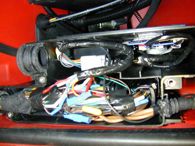
Next up is wiring the PCIII into the car for real. For this part of
the project I decide to add an electrical connector which would allow me
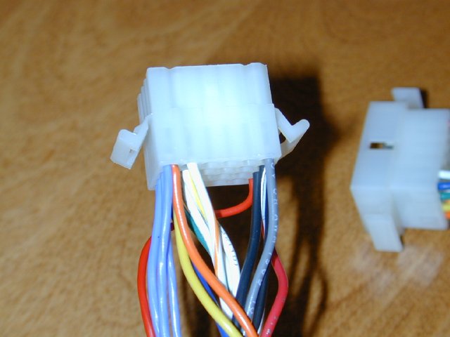
to bypass the PCIII easily if need be. I used a 24 pin molex connector
to do this. I only needed 12 connections but the 24 pin molex gives me
room to grow if I ever need to. Molex connectors aren't weatherproof but
I'm installing the PCIII into the weatherproof plastic container that the
DME is installed in. I built a new wiring harness using the wire that came
with the PCIII to keep its color codes the same.
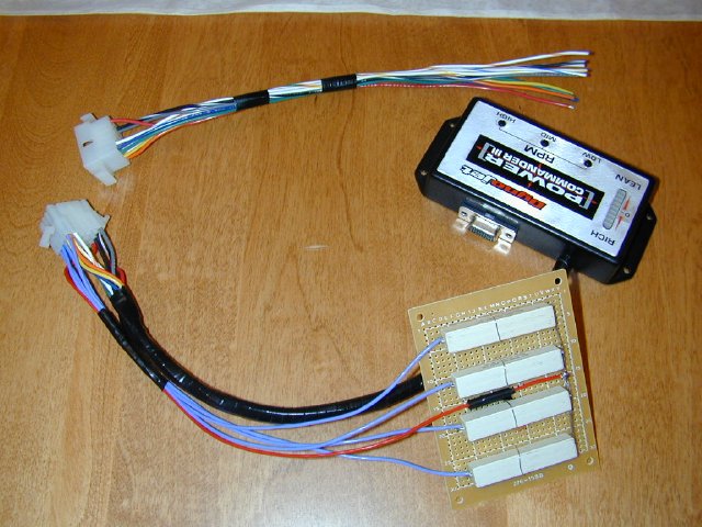
You can see the resistors which are to eliminate the fault codes in the DME. In this version I used 100ohm 10w resistors to lower the amount of heat they will generate.
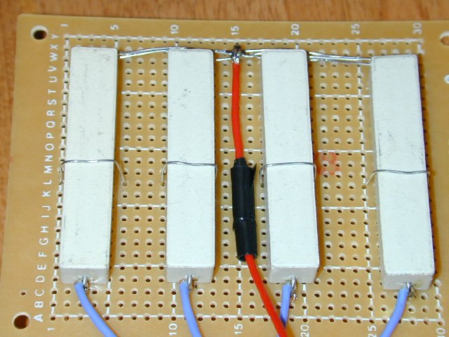
Now it is about 2w each that will go through them and that would only be if the fuel injectors were at 100% duty cycle which they won't be.
The pin out I used was
1 - Fuel Injector 1 IN
2 - Fuel Injector 2 IN
3 - Fuel Injector 3 IN
4 - Fuel Injector 4 IN
5 - Fuel Injector 1 OUT
6 - Fuel Injector 2 OUT
7 -Fuel Injector 3 OUT
8 - Fuel Injector 4 OUT
21 - TPS Signal
22- TPS Ground
23 - Ground
24 - 12v power
You can also see I tapped off pin 24 to run to the resistors, then from each resistor ran one resistor to each of the fuel injector IN lines... 1,2,3,4. When assembling the Molex I double crimped each pin and then soldered it as well to be sure I have a good connection.
You can see the wiring diagrams here.
Now for the side of the wiring harness that runs to the DME.
Molex
DME DME
wiring color
#1
pin3
brown/yellow
#2
pin32 brown/white
#3
pin31 brown/yellow
#4
pin4
brown/white
#21
pin44
brown/viloet
#22
pin71
brown/black
#23
NO DME Connection... I ran to the DME grounding plug near the strut tower
#24
#54
red/white
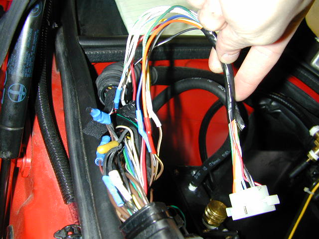
Make note that there are duplicated color codes here. If you disassemble the cover on the DME connector you can better trace what wire goes to each pin. After you find them you should nick each wire slightly and confirm it is proper by testing resistance with a multi-meter to the other end. When doing the fuel injectors make sure you are testing on the non-common side of the plug. Resistance between the wire and the injector should be well under 1 ohm. If you are measuring around 17ohms you aren't at the right place and you are seeing the connection through one of the other injectors coils. Pin 71 the TPS ground is actually a big collection of wires spliced together before the DME connector then just one wire runs to the DME. I added another wire to the collection point from the TPS ground. Pin 44 for the TPS signal doesn't agree with the Bentley wiring diagrams, the Bentley is wrong. What they say is TPS signal is actually the reference signal and vice versa for the TPS signal. NOTE: I wired the injectors 1 to 1, 2 to 2 etc, I did not try to compensate for the difference in firing order. As I thought the PCIII didn't care.
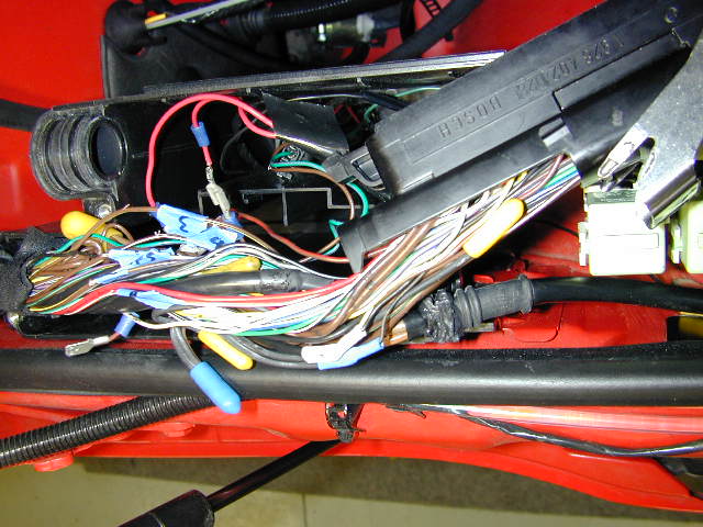
When wiring in do one connection at a time. The fuel injector lines
will need to be cut then the appropriate wires connected to each side of
the break. The other lines should not be cut, just spliced into. I use
a knife to trim away a bit of insulation and then solder the new wire directly
there.
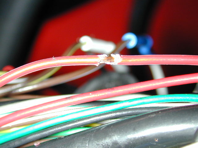
Be sure to insulate all connections well. For the fuel injector lines use heat shrink tubing and for the other connections use liquid electrical tape followed by regular electrical tape.
Do *NOT* use those cheesy push on crimp do dads. They make lousy connections that degrade over time. Do it right and solder all connections, these are after all extremely important connections. If you don't know how to solder learn on something else before trying this.
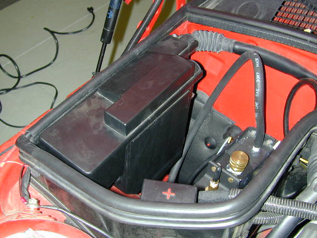
Next up was mounting the PCIII into the DMEs case.
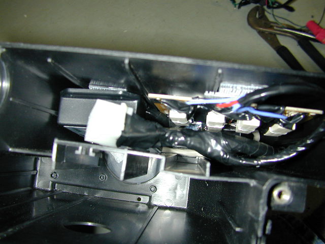
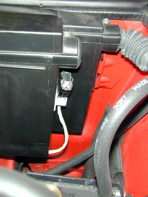
I also made a short serial cable running out the bottom of the case
so I could program the PCIII easier.
This is the DME and PCIII together in the case.
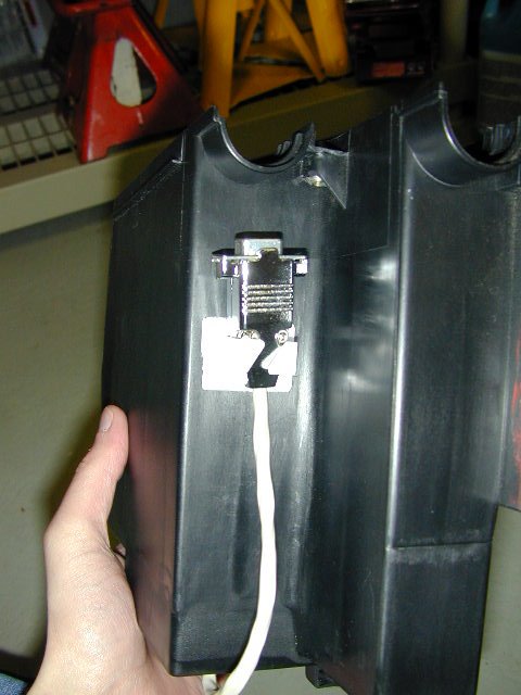
This is the case all closed up again.
Access to serial cable...
Before starting the car be sure to turn it to RUN and upload a ZERO map to the PCIII. Also go through the procedure to set throttle position before your initial start. When that is completed cross your fingers and give it a try. Mine fired right up and ran like it always did, no faults.
That is it for now. Now I can alter my mixture as desired working within the bounds of open and closed loop operation as well as the duty cycle of the fuel injectors.
I'm now working on the pieces for the next step of this project which are adapters to fit 30lb fuel injectors into my manifold, the parts to build a wide band O2 sensor. Then I need to build a frequency to voltage converter so I can use my DataQ logger to capture RPM and the output of the WB O2 sensor so I can really tune the car. Lastly I want to built a throttle stop so I can tune the car easier at the same throttle positions of the PCIII. I will be detailing each of these steps as they are completed. Additionally I might try using a MAP sensor as the 'TPS' input into the PCIII. This would let me adjust the fueling based on boost instead of TPS. I'd probably set it so atmospheric pressure was around 10% on the PCIII. That way I could remap the area under boost for larger injectors very easily, tune for the transition from vacuum to boost, and then really map out fueling as boost increases. The downside to this is it would be harder to equate the 'TPS' input into where the DME goes open loop.
Either approach should work. With the supercharger it shouldn't make too much of a difference either way. If the PCIII was being used with a turbo the MAP would probably be a better idea since boost doesn't directly correlate to throttle position because of turbo lag.
Update 4/21/02
Now that I've spent a little time using the PCIII I've already dialed
in my closed loop operation better then I was before (by about 3% confirmed
by watching LTFT) and I fixed a flat spot below 3k WOT. Before the car
sort of came on in a rush at 3k. The problem was I wasn't rich enough down
in that range. Now I dialed in about 10% more fuel between 1500 to 3000RPM
at 100% throttle and the car just takes off in that range. The PCIII makes
these sort of correction extremely easy, I'm very glad I did this mod and
it is only going to get better.
Next up is mapping out exactly where I go open loop. Using Vehicle Explorer
this will be very easy. I'll watch RPM, TPS and STFT and take it for full
RPM drives at each throttle position in the PCIII. Where the STFT drops
to 0.0 is where the car is running open loop. In that area I am free to
do whatever I want with the fueling and the DME won't car. Closed loop
operation I can just try to better dial in the mixture to 14.7:1 so the
DME will be happy. Because of the way the throttle position is calculated
in the DME it doesn't match the PCIIIs readings. The OBDII TPS tops out
at about 63.7% in my car, because the PCIII is directly mapped to the TPS
itself it goes to 100%. So I charted out what throttle positions via OBDII
match the positions in the PCIII. To help make the closed/open loop mapping
as easy as possible I'm going to build a throttle stop so I can hit the
PCIIIs throttle positions directly. I also have found that it would be
SOOO much easier if my laptop had 2 serial ports on it. Right now I have
to keep swapping cables and programs between the PCIII and the OBDII equipment.
I've ordered an Eiger Labs PCMCIA Serial port which hopefully will allow
me to have the two programs running together.
Back to Homepage
Thanks to Michael Belcher at DynoJet and Tom Mosteller
for electrical help
Copyright Shawn Fogg 2002